The menisci are semilunar fibrocartilaginous structures that play a key role in maintaining knee joint homeostasis and optimal articular function.1Located between femoral and tibial condyles, the knee menisci are directly responsible for increasing joint stability, load transmission, and distribution, shock absorption, in addition to contributing to joint nutrition, lubrication, and proprioception. These multiple and complex functions depend on the specific biomechanical properties of the menisci, which are closely related to their anatomical geometry, biochemical composition, and extracellular matrix (ECM) architecture.2,3
Owing to its deficient vascularization and, consequently, its minimal intrinsic healing capacity when damaged, the meniscal injuries usually have a poor prognosis.1Furthermore, lesions in the knee menisci commonly lead to degeneration of the underlying articular cartilage and the early onset of osteoarthritis, the most prevalent joint disease in the world, which affects a quarter of the world’s adult population and represents the second leading cause of physical disability.4–8In addition, the lack of effective and consensual therapeutic options available in clinical practice combined with the high incidence of meniscal injuries highlights the urgent and current need for the development of new treatments.9–12In this scenario, regenerative medicine technologies, such as tissue engineering (TE), have emerged as one of the most promising approaches for the management of meniscal injuries.13,14
Although a variety of TE strategies combining cells and biomaterial scaffolds have been investigated for human knee meniscus regeneration (eg, using ECM-derived biomaterials and/or synthetic polymers15) the success of this approach still strongly depends on the development of more suitable scaffolds. In this sense, one of the main challenges is to accurately reproduce the complex 3D anatomy with personalized shape and size.12,13,16Efforts to address these issues have led to an increased interest in the application of three-dimensional (3D) bioprinting in the meniscus TE field. 3D bioprinting is a biofabrication method that uses computer-aided design (CAD) and additive layer manufacturing technique to precisely deposit bioinks (basically comprising a mixture of biomaterials with cells, with or without bioactive molecules) in a predesigned manner in order to create 3D bioengineered living structures and to generate artificial tissue and organs.17,18Using this novel printing technology is possible to fabricate a patient-specific meniscal scaffold reproducing individual shape, size, and macrostructure of the native tissue.19,20
An important issue regarding the application of bioprinting in the construction of meniscus-regenerative scaffolds is that, among the variety of types of biomaterials and bioprinting methods, the extrusion of hydrogel-based bioinks is the most widely used and explored technique.21Although hydrogel-based biomaterials offer unique attributes and important advantages over other common types of regenerative scaffolds (eg, 3D and water-rich environment, high porosity, easy processing, and application versatility), in general, hydrogel-based bioprinted constructs fail to provide a scaffold that exhibits stiffness and biomechanical strength compatible with the native human meniscus.22–24Adequate mechanical properties are a fundamental prerequisite to designing scaffolds in TE, especially when applied to load-bearing tissue regeneration like knee menisci.24–26
Among the strategies reported to reinforce the structural and mechanical properties of hydrogel scaffolds are the construction of nanocomposites by incorporating stiffer nanobiomaterials, including nanoparticles and polymer nanofibers.27Nanofibrous scaffolds may be able to mimic the structural fibrillar components of the ECM, simulating the original environment and coaxing cells to behave similarly to native tissue.28However, despite reports of improvement in both the mechanical and biological performance of nanofiber-reinforced hydrogels,29–31including for meniscus TE applications,32,33the incorporation of nanofibers biomimetically organized to replicate the original architecture of the meniscal ECM has been unexplored. Since the anisotropic biomechanical properties of the knee menisci are directly dependent on the organization and orientation of their ECM fibers, the alignment of the nanofibers comprising the scaffold is another essential design consideration in tissue-engineered menisci.16,24,34Recently, our group developed a novel electrospinning method able to synthesize membranes comprised by both radially and circumferentially aligned nanofibers, representing a considerable step towards the fabrication of biomimetic scaffolds for meniscus.35
Given the above, in this study, we propose the development of a novel, bioinspired, patient-specific meniscal scaffold, in order to build, for the first time, a tissue-engineered construct capable of mimicking both the 3D macrostructure and the orientation of the main structural fibers of the native tissue. For this, our biofabrication approach was based on bioprinting of cell-laden collagen hydrogel mechanically reinforced by multilayers of biomimetically aligned electrospun polycaprolactone (PCL)/carbon nanotubes (CNT) nanofibers (an overview of our strategy is illustrated in Figure 1). Mechanical and biological assays have confirmed that this method can be an exciting strategy for building personalized biomaterial supports towards regenerative medicine. In addition, this novel meniscus-regenerative scaffold presented favorable characteristics for future in vivo applications aiming at meniscus TE.
Figure 1 Overview of biofabrication strategy to create a novel patient-specific meniscal scaffold based on bioprinting of cell-laden type 1 collagen hydrogel reinforced by multilayers of biomimetically aligned electrospun PCL/CNT nanofibers. |
The biomimetically aligned nanofibrous mats, composed of PCL and CNT, were fabricated by a specific electrospinning system previously developed by our research group and following the reported protocol.35,36Basically, the electrospinning setup was comprised of a high voltage power supply (CZE1000R, Spellman), a syringe pump (KDS100, KD Scientific), a glass syringe (5 mL, BD) fitted with a metal needle (19G, Inbras) and a modified fiber collector connected to a motor (W22, WEG). The fiber collector consists of an external hollow cylindrical metallic device with a central rod and a mobile internal metallic cylinder with a central hole.
For preparing the PCL/CNT solution, Multiwall Carbon Nanotubes (MWCNTs), previously synthesized and functionalized by oxygen plasma,37,38was ultrasonicated for 60 minutes in dimethylformamide (DMF, Sigma-Aldrich) and then added to PCL solution in which PCL pellets (molecular weight of 80 kDa, Sigma-Aldrich) were dissolved in chloroform (Sigma-Aldrich). The PCL and CNT solutions were mixed in a volume ratio of 3:1 in order to obtain a final solution with a concentration of 120 mg·mL−1for PCL and 1 mg·mL−1for CNT. Subsequently, this solution was loaded in the glass syringe and electrospun in two steps: In step 1, the metallic collector without the internal device and in a stationary way was used to create a structure such as a peripheral ring and a central point electrode. In this way, it is possible to synthesize radially aligned nanofibers. Then, in step 2, the internal device is used by turning the collector into a rotating solid cylinder to electrospun circumferentially aligned nanofibers on top of the previously produced radially aligned nanofibers; thus, simulating the fiber organization of the native ECM of the knee menisci. The electrospinning parameters are described in Table 1.
Table 1 Electrospinning Process Parameters of Aligned Nanofibrous Mats |
To incorporate hydrophilicity and improve wettability and integration with hydrogel layers, the electrospun mats were treated by oxygen plasma on both the upper and lower surfaces, using the following parameters: 0.3 mbar pressure, 0.0012 kg·sec−1O2flow, 489–562 V voltage, 0.07–0.10 A electric current, at ~58°C for 5 minutes.39
The construction of the biomimetic scaffold was based on incorporating multilayers of aligned PCL/CNT nanofibrous mats between the bioprinted hydrogel layers. The insertion of nanofibrous layers was performed during the hydrogel bioprinting process. For the printing of hydrogel layers, a highly concentrated type 1 collagen bioink (Lifeink®200, Advanced BioMatrix) was homogeneously blended with Phosphate Buffered Saline (PBS) (5:2 volume ratio of Lifeink®200:PBS) to obtain a bioink at a final concentration of 25 mg·mL−1as recommended by the manufacturer.
3D bioprinting was conducted using an extrusion 3D bioprinter (BioEdPrinterV4, BioEdTech) with the following optimized parameters: 4°C printhead temperature, 37°C printing platform, 6 mm·s−1nozzle movement speed, 0.26 mm nozzle inner diameter, 0.2 mm layer height, and 40% infill density. After the bioprinting process, the scaffolds were kept at 37 °C for 45–60 min for the collagen hydrogel crosslinking.
To compare the effect of aligned nanofibrous mats between the hydrogel, scaffolds were constructed based on different ratios of nanofiber layers: one nanofiber mat layer to two bioprinted hydrogel layer (hydrogel:nanofibers 2:1), one nanofiber mat layer to four layers of bioprinted hydrogel (hydrogel:nanofibers 4:1), bioprinted hydrogel without nanofibers (hydrogel:nanofibers 1:0).
To evaluate the structural integrity of the scaffolds, cylinder samples of hydrogel:nanofibers 2:1, hydrogel:nanofibers 4:1, and hydrogel:nanofibers 1:0 (8 mm diameter x 4 mm height) were fabricated. Digital images of top views of the scaffolds were captured before and after the hydrogel crosslinking process, and cross-sectional surface areas were analyzed using ImageJ software. The total macroscopic scaffold shrinkage was calculated using the following equation:
A comparison between the forms of the 3D digital model and the samples immediately after the printing process was also conducted to analyze the shape fidelity.
Additionally, images obtained from an optical microscope (DM2700 M, Leica) were used to observe the structure of the construct in more detail.
Cylinder samples of hydrogel:nanofibers 2:1, hydrogel:nanofibers 4:1, and hydrogel:nanofibers 1:0 (8 mm diameter x 4 mm height) fully swollen were prepared for uniaxial unconfined compression tests. Compressive properties of the scaffolds were obtained using a Universal Testing System (model 3342 equipped with Bluehill®software package, Instron) with a 100 N load cell. To simulate the physiological load to which the human meniscus is subjected, the strain rate and maximum strain were set to 50%·min−1and 40%, respectively.40From the stress vs strain curve created, the compressive modulus was determined as the stress-strain curve slope at 30% strain.
The study was conducted according to the Guide for the Care, and Use of Laboratory Animals approved by the ethics committee (CEUA-ICT-UNESP, Protocol 07/2017).
Mesenchymal stem cells (MSCs) were harvested from the bone marrow of the femur and tibia of Wistar rats (90 days old, 130–150 g, Rattus norvegicus Albinus). Briefly, after bone acquisition and cleaning with PBS, ethanol 70%, 2.5% chlorhexidine, Minimum Essential Medium Eagle - alpha modification (α-MEM, Gibco-Invitrogen) and 1% penicillin-streptomycin (Gibco), the proximal end of the femur and the distal end of the tibia was cut. In the region opposite to the cut, with the aid of an 18G needle, Dulbecco’s modified Eagle’s medium (DMEM, Gibco-Invitrogen) was injected to remove the bone marrow. Subsequently, the bone marrow suspension was mechanically dissociated with 16–20G needles and centrifuged for 5 minutes at 500g. Then, the MSCs were resuspended in culture media composed of DMEM supplemented with 10% (v/v) fetal bovine serum (FBS, Gibco, USA), 1 mM of L-glutamine, and 1% antibiotic-antimycotic solution (Gibco), counted and seeded in culture flasks. The cells were cultured using standard tissue culture techniques in a controlled atmosphere (5% CO2atmosphere at 37°C), and the culture medium was changed every 2 days. After 80% confluence, the MSC were trypsinized using a trypsin/EDTA solution (0.25% trypsin, 4 mM EDTA; Gibco) and seeded at the same density into new cell culture flasks. The cells were expanded by repeating this process until, at the most, the fifth passage (P5).

MSCs trypsinized, counted, and resuspended in the culture medium were used for cell-laden bio-ink preparation according to the manufacturer’s instructions. The MSC suspension was loaded into a sterile syringe attached to a syringe containing Lifeink®200by a sterile coupler. Then, the cell suspension and Lifeink®200 were mixed (5:2 volume ratio of Lifeink®200: cell suspension) to obtain a homogenous bioink at a final cell and type I collagen concentration of 6×10⁶cells·mL−1and 25 mg·mL−1, respectively. Finally, the cell-laden bioink was loaded into a 5 mL syringe compatible with the 3D BioEdPrinterV4.
For the cell viability experiments, 3D bioprinted cell-laden samples of hydrogel:nanofibers 2:1, hydrogel:nanofibers 4:1, and hydrogel:nanofibers 1:0 (8 mm diameter x 4 mm height) were prepared using the same method and parameters described previously (section 2.2). Before use in cell assays, PCL/CNT nanofiber mats were subjected to a disinfection process in which samples were soaked in ethanol 70% for 30 minutes, then rinsed twice in PBS, and lastly, kept in laminar flow under UV light for 30 minutes on each side.41,42
After the bioprinting, the scaffolds were transferred to a 48-well cell culture plate, kept at 37 °C for 45–60 min for the hydrogel crosslinking, and then immersed in culture media. Bioprinted scaffolds were incubated in culture media for 1 and 7 days at 37 °C in a 5% CO2incubator.
Cell viability was measured by Live/Dead staining. Briefly, at the designated time points, cell-laden scaffolds were washed with PBS and incubated with green-fluorescent calcein-AM (Thermo Fisher Scientific) at 0.5 μg·mL−1and red-fluorescent ethidium homodimer-1 (EthD-1, Thermo Fisher Scientific) at 2.0 μg·mL−1for 30 min at 37°C in the dark. Subsequently, the cell-laden scaffolds were rinsed again in PBS, and stained cells were immediately viewed under an inverted fluorescence microscope (Eclipse TI, Nikon). The images captured were analyzed by ImageJ software, and the cell viability was determined based on the percentage of live cells (green) and dead cells (red) concerning the total number of cells.
All the experiments were performed in triplicate, and the data were expressed as the mean ± standard deviations. Statistical differences between values were determined by one-way analysis of variance (ANOVA) followed by Tukey post hoc test using GraphPad Prism software (GraphPad Software Inc.). A value of p<0.05 was considered statistically significant.
To create a 3D digital model of the human knee meniscus, Digital Imaging and Communications in Medicine (DICOM) datasets obtained from Magnetic Resonance Imaging (MRI) scan of the right knee joint of an unidentified 30-year-old subject were processed using InVesalius software (CTI Renato Archer), an open-source software tool that allows the visualization, analysis and 3D reconstruction of medical images from DICOM files. Automatic threshold segmentation and manual adjustments were performed to generate a 3D model of the medial meniscus of the knee, exported as an STL file.
Subsequently, the STL model was processed using Fusion 360 software (Autodesk). In this step, the 3D digital meniscus model was sliced into a sequence of two-dimensional cross-sections (a difference of 0.2 mm in height between the cross-sections). Then, from these 2D models, metal sheets were produced by a metal laser cutting machine (TruLaser 3030, TRUMPF). These metal sheets were attached to the electrospinning collector’s surface, and the protocol previously described in section 2.1 was performed to create nanofibrous mats with the patient-specific dimensions of the medial meniscus.
Lastly, the patient-specific biomimetic meniscal scaffold based on hydrogel:nanofibers 2:1 and hydrogel:nanofibers 1:0 were bioprinted following the processes described in section 2.2.
The first step of this research was to investigate the feasibility of this specific biofabrication strategy and the influence of nanofiber layers between bioprinted hydrogel layers. For this purpose, we produce aligned PCL/CNT nanofiber sheets through a previously designed electrospinning system, which has proven to be able to produce fibers bioinspired in the organization of the major structural components of the meniscus ECM: thicker fibers aligned circumferentially (deepest) and thinner fibers aligned radially (more superficial) (Figure 2A).36,43Circular samples of these specific nanofibrous mats (8 mm diameter x ~0.01 mm thickness) (Figure 2B) were manually inserted layer-by-layer in different proportions during the hydrogel printing process. If, on the one hand, the thin thickness of the electrospun nanofibrous mats provide a practical difficulty for its handling during the manufacturing process, on the other hand, this same characteristic facilitated its integration process with the hydrogel since the nanofibrous sheets were highly flexible and were able to adapt easily to the surface shape of the printed hydrogels layers (Figure 2C).
Figure 2 (A) SEM image of electrospun PCL/CNT nanofibers aligned in different orientations, circumferentially (average fibers diameter 368 ± 84 nm) and radially (average fibers diameter 193 ± 68 nm) using previously designed electrospinning process. (B) Macroscopic appearance of biomimetic nanofibrous mats cut into cylindrical samples. (C) Side view of the hydrogel:nanofiber sample illustrating the nanofiber mats between the printed hydrogel layers. |
It is noteworthy that the adequate adhesion between the PCL/CNT nanofibers and the hydrogel was only achieved with the functionalization of the electrospun mats. Because of the high hydrophobicity of PCL, our previous attempts to integrate nonfunctionalized nanofibrous mats with type 1 collagen hydrogel failed, showing delamination. The same strategy used in this study to improve the wettability of polymeric fibers by introducing oxygen-containing functional groups has been successfully used by other studies to increase PCL surface hydrophilicity and enhance the use of this polymer in TE.30,39,44–46
The choice for this combination of biomaterials (PCL/CNT) was based on previous studies in which, by this proposed methodology, this nanocomposite proved viable for the fabrication of biomimetic scaffolds with optimized mechanical properties without negatively affecting the viability of MSCs seeded on structure.36Still, in further studies, we strongly recommend investigating other nanocomposites using the same biofabrication method in order to minimize some disadvantages of these biomaterials, such as the hydrophobicity of PCL47and the potential long-term toxicity of CNT.48,49
The macroscopic aspect of hydrogels bioprinted with different proportions of nanofibrous mats (~4 mm height, 20 layers), immediately after the manufacturing process, are illustrated in Figure 3A. The influence of nanofiber mats between the hydrogel layers on the three-dimensional structure of the scaffold was analyzed using the macroscopic shape fidelity (top view) and shrinkage test. Compared with the 2D surface area of the digital model, the nanofiber-free bioprinted type 1 collagen hydrogel showed a statistically significant difference in its shape immediately after the printing process (hydrogel:nanofibers 1:0, 21.0% size mismatch) (Figure 3B). Although pure type 1 collagen hydrogel is considered an excellent biomaterial as it provides an appropriate environment for the adhesion and proliferation of living cells (type 1 collagen naturally corresponds to the main component of the meniscal ECM2), its use as a bioink is limited since this hydrogel in lower concentrations does not present good rheological properties to create 3D scaffolds over 1–2 mm thick, often showing structural collapse.50,51Possible options to overcome this limitation are using supporting materials based on other types of hydrogels (eg, FRESH method, freeform reversible embedding of suspended hydrogels52,53) or fibers. In this present study, with the incorporation of electrospun nanofibrous mats between the hydrogel layers, our printed constructs were able to maintain their shape closer to the pre-designed cylindrical scaffold (hydrogel:nanofibers 4:1 and hydrogel:nanofibers 2:1, 2.1% and 0.7%, respectively), evidencing the nanofiber-hydrogel integration and its positive effect on structural robustness. To reinforce these findings, digital photos from the top of the bioprinted scaffolds were obtained before and after the crosslinking process in order to assess the decrease in sample size (Figure 3A). Figure 3C illustrates comparatively the surface area of the cross-section (top) of the scaffolds, as well as the total percentage of shrinkage. While nanofiber-free hydrogels showed considerable shrinkage (19.8%), incorporating nanofibrous mats inside the hydrogel provided greater maintenance of the scaffold morphology, presenting a lower post-crosslink shrinkage rate (hydrogel:nanofibers 4:1, 1.79% and hydrogel:nanofibers 2:1, 1.20%). The collagen hydrogel contraction, which has also been found in previous studies,54,55is considered one of the main barriers to applying this biomaterial in TE field. This improvement in shape uniformity after incorporating fibers, a phenomenon also observed by other authors,30,56may be related to the adhesion of hydrogel layers to structural nanofibers, and presents a promising way to prevent the collagen shrinkage issue.
Figure 3 Morphological characterization of printed type 1 collagen hydrogel incorporated with different amounts of PCL/CNT nanofibrous mats. (A) Schematic illustration of printed hydrogel with varying ratios of nanofiber layers and top view of scaffolds shape before and after the crosslinking process (scale bar: 4 mm). (B) Quantitative analysis of shape fidelity immediately after the printing process (percentage values represent the relative increase in the cross-sectional surface area compared to the digital model). (C) Shrinkage test before and after the hydrogel crosslinking process (***p < 0.001). |
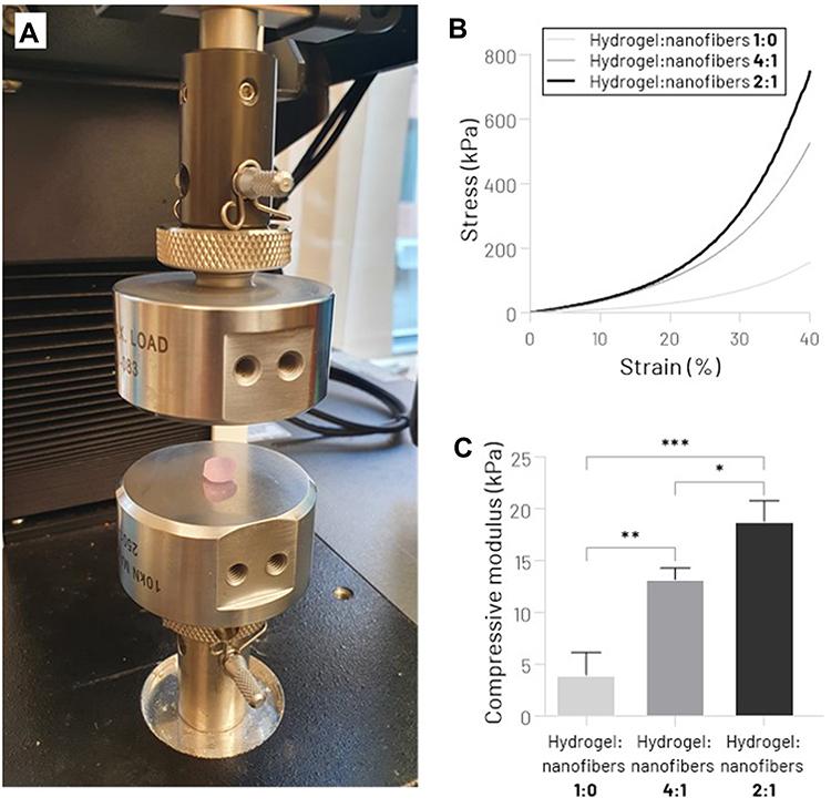
The mechanical performance of the bioprinted collagen hydrogel reinforced by multilayers of aligned electrospun PCL/CNT nanofibers was evaluated using a uniaxial compression test (Figure 4A). Predictably, the presence of the nanofibrous mats significantly improved the mechanical properties of scaffolds. According to the stress-strain curve (Figure 4B), it is possible to notice an improvement in the mechanical stiffness from the increase of nanofiber sheets between the hydrogel layers. Higher values of compressive modulus were observed in the hydrogel:nanofibers 2:1, 18.7 ± 2.0 kPa, while hydrogel:nanofibers 4:1, and hydrogel:nanofibers 1:0 (nanofibers-free) presented 13.2 ± 1.1 kPa and 3.9 ± 2.2 kPa, respectively (Figure 4C). These results, which corroborate previous studies that used nanofiber-reinforced hydrogels,30,57may have been due to the better dissipation of the compressive load along nanofibers stronger than the soft hydrogel. Adjusting the mechanical behavior of the scaffold plays a key role not only in providing adequate mechanical support for new tissue growth but also in modulating the cellular response.26Although the mechanical performance is not directly compatible with native human knee menisci (compressive modulus 90–220 kPa58,59), the tunable mechanical properties of the scaffold produced by this strategy allow us to infer that in future studies, it will be possible to biomimic the native tissue stiffness by varying the proportion of nanofiber membranes, as well as using other tougher biomaterials as hydrogel matrix.
Figure 4 Mechanical assessment of hydrogel:nanofibers scaffolds. (A) Unconfined Compression Testing System. (B) Stress−strain curve. (C) Compressive Young’s modulus (*p < 0.05, **p < 0.01, ***p < 0.001). |
In vitro biological performance of PCL/CNT fiber-reinforced bioprinted hydrogel was assessed using the Live/Dead assay. Fluorescence images of live/dead cells in distinct scaffold regions (central core and outer region) are shown in Figure 5A. Quantitative cell viability results measured by digital image analysis (percentage of live vs dead cells) demonstrated that MSCs within scaffolds, with or without nanofiber membranes, remained viable (>80%) after 1 and 7 days (Figure 5B). These findings suggest that the viability of MSCs is not significantly affected either by the stress caused during the bioprinting process or by the incorporation of specific amounts of electrospun PCL/CNT nanofibrous mats. The results are especially important for the future of TE of the knee meniscus since the MSCs are a viable cell source with a unique intrinsic therapeutic potential for meniscal regeneration.60,61As expected, after 7 days of culture, superior cell viability was observed closer to the outer edge of the scaffold (Figure 5C), possibly due to the predictable decrease in nutrient and oxygen diffusion in the central regions of the scaffold; an occurrence frequently observed in studies with cell-laden hydrogel cultured under static conditions.33,62,63The use of a dynamic fluids environment, such as bioreactor systems, could minimize this negative effect and improve cell viability and proliferation in the scaffold core.64However, no statistically significant differences were found comparing the three different hydrogel:nanofibers scaffolds; reinforcing the lack of adverse effects of the presence of PCL/CNT nanofiber layers on the cell viability of bioprinted type 1 collagen hydrogel.
Figure 5 Cell viability analysis by live/dead assay. (A) Fluorescent microscopy images of live/dead staining of MSCs seeded on the different hydrogels:nanofibers groups, 1 and 7 days after the scaffolds biofabrication process (the green color indicates live cells, and the red color indicates dead cells) (scale bar: 100 μm). (B) Percentage cell viability after 1 and 7 days in cell culture. (C) Percentage cell viability after 7 days in cell culture comparing outer edge (external) and central region (internal) (*p < 0.05, **p < 0.01). |
Based on the experiments above, a 3D patient-specific biomimetic meniscal scaffold was fabricated using a digital meniscus model obtained by MRI of a healthy human knee (Figure 6A-C). We have satisfactorily reconstructed a custom-made 3D model of the human meniscus using a free and open-source software (Figure 6D). It is essential to highlight that although the automatic segmentation provided by the InVesalius software offered an excellent starting point for 3D modeling, additional manual segmentation was mandatory, requiring some experience and anatomical knowledge of the tissue. Taking into account the macroscopic size and shape compatibility of meniscal implants are crucial for the biomechanical functioning of the structure and, therefore, for the success of the application,20,24the 3D model reconstruction of the original tissue using methods that do not require expensive and sophisticated software represents a significant advance towards the development of patient-specific scaffolds and prostheses for the treatment of meniscal injuries.
Figure 6 Design of patient-specific 3D digital model of the human knee meniscus. Illustration of medial meniscus segmentation from MRI images of the 3 distinct planes (A) axial plane; (B) Sagittal plane; and (C) Coronal plane) the right knee of a subject. (D) The reconstructed 3D digital model of the medial meniscus. |
Predicated on previously obtained results, hydrogel:nanofibers 1:0 and hydrogel:nanofibers 4:1 group were chosen for the bioprinting of engineered 3D meniscus. Firstly, metal sheets produced with specific 2D dimensions from different layers of the patient’s medial meniscus were coupled to the surface of the electrospinning system collector, allowing the construction of biomimetically aligned electrospun nanofibrous mats with a size compatible with the 3D model (Figure 7A).
Figure 7 (A) Metal sheets used as electrospinning system collector (top row) for fabrication of the biomimetically aligned electrospun nanofibrous mats with custom dimensions (bottom row) (scale bar: 15 mm). (B) Photograph of a patient-specific bioprinted meniscal scaffold (hydrogel:nanofiber 4:1) (scale bar: 5 mm). (C) Top view of bioprinted meniscal scaffold based on nanofiber-free collagen hydrogel (hydrogel:nanofiber 1:0) and reinforced with biomimetic nanofibrous layers (hydrogel:nanofiber 4:1); compared to the reconstructed digital model (Orange line). (D) Quantitative analysis of shape fidelity of 2D area of the top of the bioprinted meniscal scaffolds (percentage values represent the relative increase in the cross-sectional surface area compared to the digital model) (the Orange dashed line represents the cross-sectional surface area of the digital template) (*p < 0.05). |
Finally, the patient-specific 3D meniscal scaffold based on cell-laden hydrogel reinforced by biomimetically aligned electrospun nanofibers was successfully bioprinted (Figure 7B). Compared with the pure collagen hydrogel bioprinting, it was possible to visually notice (Figure 7C) and by quantitative analysis of the shape fidelity (Figure 7D) that the introduction of nanofiber layers helped the bioprinted meniscus maintain its 3D structure more faithfully to the designed model. This finding is in accordance with the results previously reported in this study. Although the incorporation of nanofibers during bioprinting has been a relatively complicated process, mainly due to the difficulty in handling the thin nanofibrous membranes, the biofabrication strategy developed in this study proved to be suitable for the construction of personalized regenerative implants for application in meniscus TE.
Additionally, in subsequent works, in addition to the fibrous structure of the native tissue, the heterogeneous distribution of glycosaminoglycans is also worth replicating, since this relevant constituent of the meniscal ECM also plays a fundamental role in the mechanical function of the tissue.65
Furthermore, despite the proof of concept in this work having been performed by printing a whole meniscus, further on, the applications of this technique may also be related to the fabrication of small fragments, with specific size and shape of the damaged meniscus region.
In conclusion, the present study demonstrated the feasibility of fabricating a bioinspired patient-specific meniscus-regenerative scaffold based on the association of bioprinted cell-laden hydrogel and biomimetically aligned electrospun nanofibrous mats from digital 3D meniscus model obtained by segmentation of MRI datasets using free and open-source software. Incorporating nanofibrous mats between the hydrogel layers enhanced mechanical properties and macroscopic 3D structure of the scaffold without affecting MSCs viability, evidencing the immense potential of this biofabrication concept for regenerative medicine especially for knee meniscus applications.
In the future, before proceeding with in vivo studies and clinical translation, further studies using this strategy should be conducted in order to create scaffolds with adequate mechanical strength to withstand the stress generated by physiological loads imposed on the knee menisci. Furthermore, the poor handling properties of nanofibrous membranes encourages us to develop new methods and technique to integrate nanofibers bioinspired by the architecture of the native ECM into bioprinted hydrogels.